 |
|
 07-31-2020, 02:26 AM
|
#1
|
|
Member
Join Date: Jun 2013
Posts: 37
|
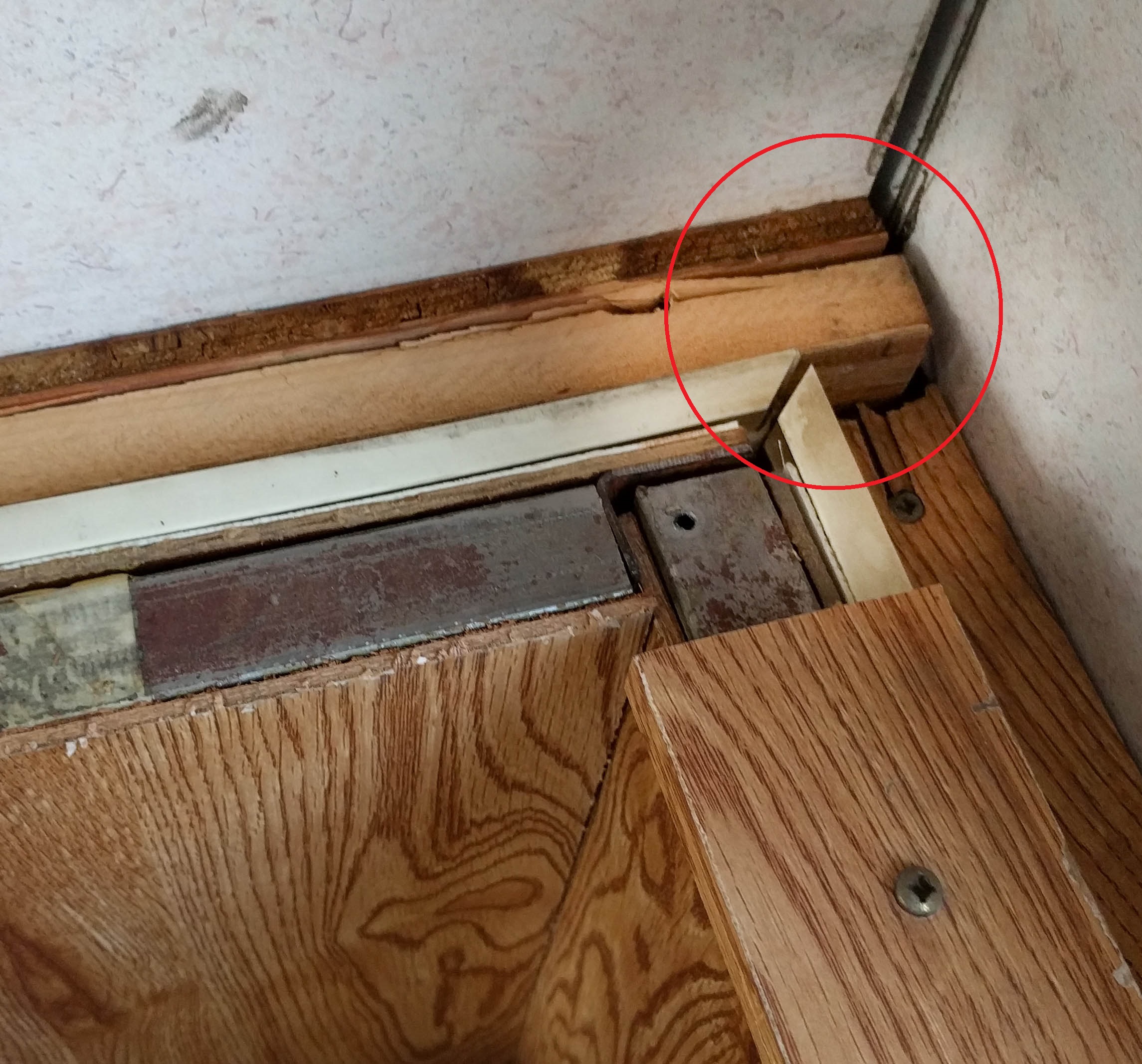
 Front Upper Corner Construction
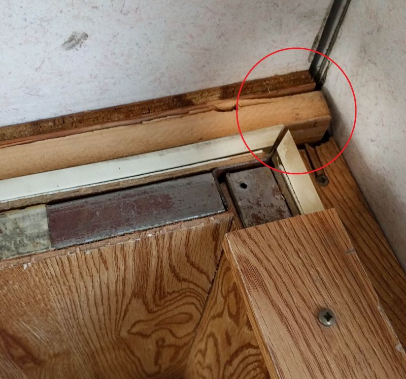
Does someone have photos or know how the front corner is constructed? My front right corner is structurally broken and my previous two repairs have failed due to the weight of the top resting on the tonque bending my steel brackets designed to fix the corner. perhaps the steel cables are supposed to support the weight instead of the rubber pads on the tongue?
|

|

|
|
07-31-2020, 09:48 AM
|
#2
|
|
Site Team
Join Date: Jul 2010
Location: Pine, AZ
Posts: 4,548
|
If you post a picture of the problem area it might help us help you with some ideas. It sounds like your trailer does not have the "outriggers" on the sides that my trailer has that support the top when the trailer top is lowered. The cables should NOT be supporting the weight of the top when it is down as far as I know.
- Jack
__________________
__________________
Hi-Lo 1707T - Tire Minder TPMS on Tow Vehicle and Trailer, 300W Solar Battery Charger, Equal-i-zer WDH, Progressive Dynamics Converter, Fan-Tastic Fan, LiFePO4 battery 12V DC Electrical System
2014 F150 Platinum 4x4 3.5L EcoBoost SCrew
|
|
|
|
|
07-31-2020, 01:57 PM
|
#3
|
|
Member
Join Date: Jun 2013
Posts: 37
|
Quote:
Originally Posted by JackandJanet

If you post a picture of the problem area it might help us help you with some ideas.
|
I did post the photo above with the circled area, which is the front right corner. Are you able to see that photo, or should I zoom out? The circled section should be flush with no offset. The corner itself can't be photographed without removing the top. The lower section corner is intact, but the upper section corner is broken.
The main issue I have is that the design is so weak (made with 1x2), that I'm having trouble understanding how it's supposed to have held together.
Quote:
Originally Posted by JackandJanet
It sounds like your trailer does not have the "outriggers" on the sides that my trailer has that support the top when the trailer top is lowered. The cables should NOT be supporting the weight of the top when it is down as far as I know.
|
Yes, my trailer rests on the rear bumper frame extensions, two outriggers aft of center, and then on the tongue triangle in the front. Lowering it all of the way crushes my dual steel L plate fix. My next thought is sandwiching the right side and forward side of the corner in 4 feet of unistrut on each using thru-bolts. The right side would rest on the front side to prevent the sag that is crushing the front of the trailer.
|
|
|
|
|
07-31-2020, 02:20 PM
|
#4
|
|
Site Team
Join Date: Jul 2010
Location: Pine, AZ
Posts: 4,548
|
I see your picture now. For some reason, it was not there when I posted my reply.
That IS a tough place to repair. I think I'd try to place L-plates (heavy ones) on both the top and bottom of that joint and then bolt through them.
I don't really understand how you would use Unistruts, but if you can see how to do it, they would be strong too.
So, the top is supported at the front and the rear, but not at all on the sides, is that how it is? I think HiLo figured out at one point that your design was weak and added the side supports (outriggers).
|
|
|
|
|
08-01-2020, 12:54 AM
|
#5
|
|
Member
Join Date: Jun 2013
Posts: 37
|
It has the side outriggers, but they are aft of the door. It ideally would need two more, which I suppose is another way to fix the issue. The L plates is what bent. I had one on top and one underneath. They were only 1/8" thick. 1/4" might work. Essentially that is what I would be doing with the unistrut, but they'd run 4 feet in each direction and then overlapped rather than welding. I was originally going to weld a corner and then add a vertical gusset to the corner, but a friend suggested overlapping one over the other so that when the force is applied upward on the forward unistrut it would stop at the longitudinal unistrut brace.
I still scratch my head about the original structural design of the corner.
|
|
|
|
|
08-01-2020, 09:48 AM
|
#6
|
|
Site Team
Join Date: Jul 2010
Location: Pine, AZ
Posts: 4,548
|
OK, NOW I think I understand how you would use the Unistruts.
I'm puzzled you have only one set of outriggers, and they are at the rear? Or, am I still misunderstanding this? If so, do the outriggers provide the majority of the support when the top is down? Do the outriggers still have their hard rubber pads, and is there a corresponding pad on the bottom edge of the top that mates with it? This pad can deteriorate and may be missing.
I replaced the pads on one side of my trailer because they had deteriorated and were in danger of falling off. I used hockey pucks that I split with a saw to 1/2 thickness. Other members have suggested using a piece of tire tread.
The majority of the weight of the top should be supported at the sides, not at the ends. And missing rubber pads will cause that to not happen.
Looking at your picture, it appears there is no support at that side, when the top is down.
- Jack
|
|
|
|
|
08-01-2020, 07:59 PM
|
#7
|
|
Member
Join Date: Jun 2013
Posts: 37
|
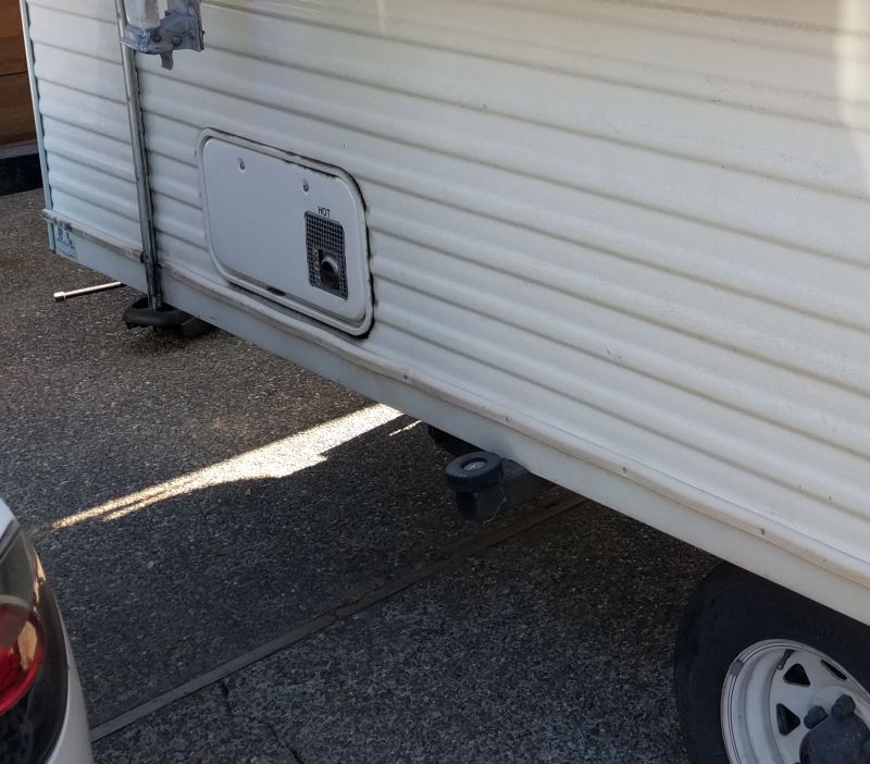
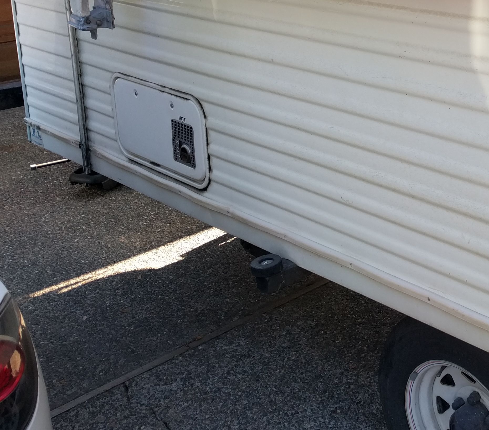
This picture shows the only outriggers:
|
|
|
|
|
08-01-2020, 08:02 PM
|
#8
|
|
Member
Join Date: Jun 2013
Posts: 37
|
This photo shows the front rests where the problem is occuring:
|
|
|
|
|
08-01-2020, 08:04 PM
|
#9
|
|
Member
Join Date: Jun 2013
Posts: 37
|
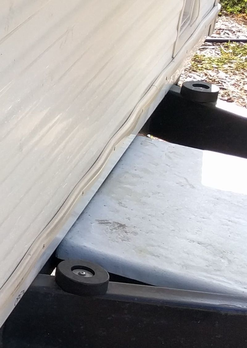
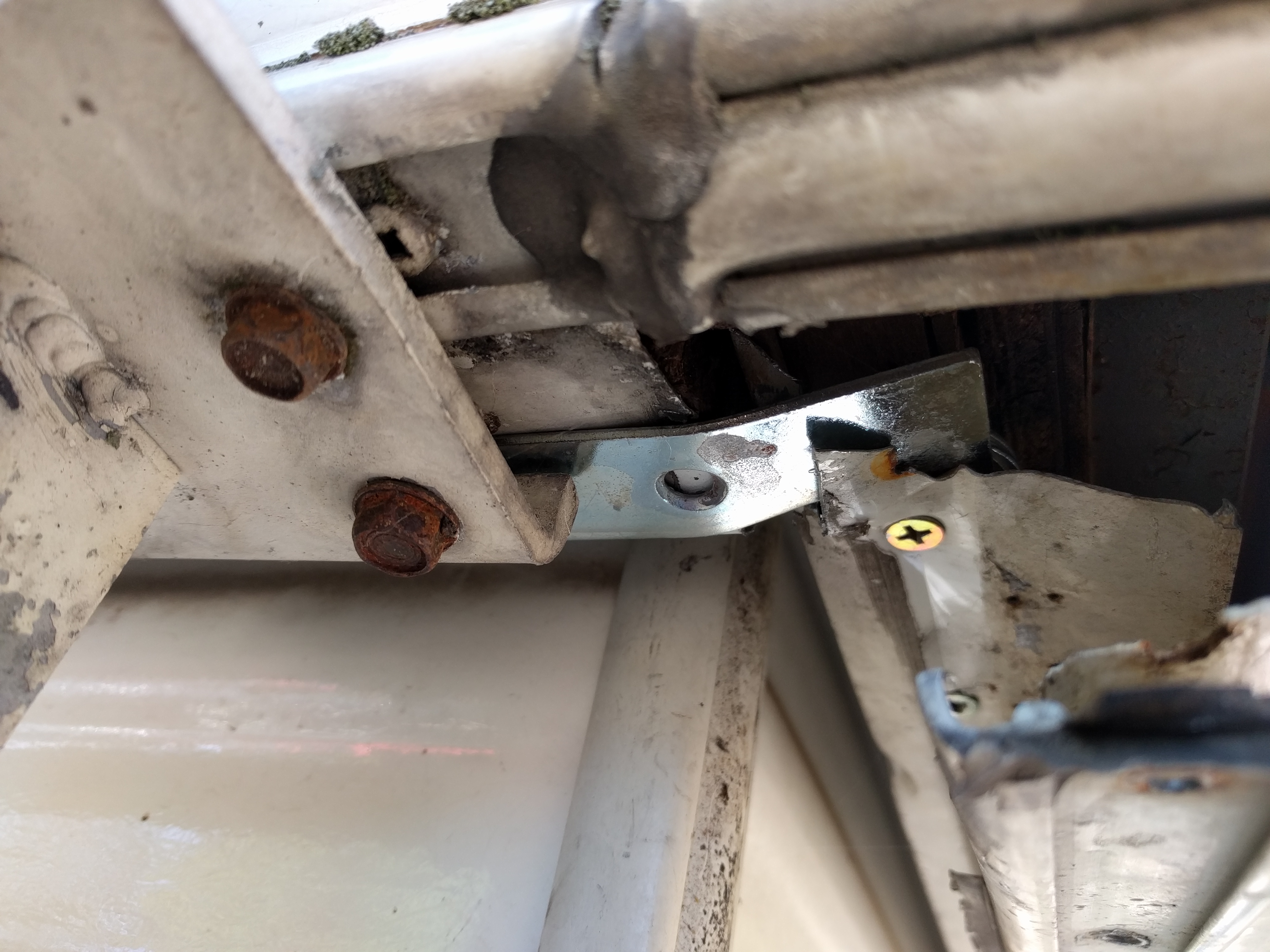
The image below shows the underside where I had installed a bracket to brace the corner.
Aws you can see this and the mirror of this bracket I installed on the inside failed by bending when the top was lowerd.

|
|
|
|
|
08-01-2020, 08:07 PM
|
#10
|
|
Member
Join Date: Jun 2013
Posts: 37
|
I couldn't think of any reason at the time to not use the pucks at full height, but I suppose if the seal between the top and bottom were functional, maybe that would be the reason.
|
|
|
|
|
08-01-2020, 10:41 PM
|
#11
|
|
Site Team
Join Date: Jul 2010
Location: Pine, AZ
Posts: 4,548
|
OK, this is just weird! I don't see any pictures in your thread again, but I see them in other threads. I'll check again tomorrow on this PC (a notepad) and on my desktop downstairs. I don't have a clue why the pictures should be invisible to me (a site team member). There's not even a "broken" link symbol to indicate there should be a picture there. I've tried refreshing the tab and that doesn't do anything either.
Edit: I found the problem! It's in Firefox. I opened this thread in Chrome and I see all the pictures! Double Edit: They show up in Edge too!
I cut my hockey pucks to match the height of the original rubber pads on the outriggers. I only replaced ones on one side, so I didn't want the top to sit "tilted". As for as I know, there's no seal between the top and bottom when the top is lowered.
Edit: And, I see a definite problem. Your top is not resting on the hockey pucks at all when the top is down! They are supposed to provide a bit of a "cushion" to the top when you are underway on the road. If you only have a rear outrigger, then the weight of the front is borne completely by the front part of the top. It should be supporting the sides, near the vertical track that the guides in the top slide on.
It would be best if you could figure out a way to add a set of outriggers in that area to match the ones you have in the rear.
I think if you were to use heavier thickness L-plates (or maybe double them) it would fix your broken corner joint. Put them top and bottom and bolt through the entire structure.
- Jack
|
|
|
|
|
08-01-2020, 11:05 PM
|
#12
|
|
Site Team
Join Date: Jul 2010
Location: Pine, AZ
Posts: 4,548
|
Actually, I now like your idea of Unistruts since they have a U-shape. Steel with an L-shape that fits along the side and top/bottom of the frame would work too, but I think you would have to "lap" it at the corner too, since I've only seen straight sections. Apply these top and bottom and lap them so the side can't drop below the front when all the weight is being borne by the front.
However, I'm not really sure this kind of fix will work long term by itself. You need outriggers at the front side!
- Jack
|
|
|
|
|
08-01-2020, 11:13 PM
|
#13
|
|
Site Team
Join Date: Jul 2010
Location: Pine, AZ
Posts: 4,548
|
Are the one set of outriggers about halfway along the side? If so, perhaps if the hockey pucks on these were moved inwards so the top sat on them, it would take the weight off the ends. You could try this - see if the front and rear of the top is suspended in mid-air if the hockey pucks are moved so they support the top on the outrigger.
If so, I'd still add rubber bumpers (thinner ones) at the front and rear to take care of any "rocking" impacts that might occur during travel.
- Jack
|
|
|
|
|
08-02-2020, 04:01 PM
|
#14
|
|
Site Team
Join Date: Jul 2010
Location: Pine, AZ
Posts: 4,548
|
Interesting! I'm looking at your thread on my desktop, using Firefox and I see ALL the pictures. I must have an add-on in my notepad version that kills yours, but not others!
At the risk of my life, I've got pictures here. Since the outbreak of Covid, I have done nothing with my trailer and it has been covered since last fall. When I pulled up the cover, so I could raise the top, I found, to my horror, a 4" wide wasp nest inside it with 10 or more wasps in residence. After running for my life, and not being stung (I must be living virtuously), I returned with wasp spray that I used up trying to kill all the critters. They must be tougher than normal - I knocked some of them down but they were able to then fly away! There are still five or more interested in the area where the nest was, and, I MAY have another nest under the front of the trailer. 
However, as amusing as this is, it doesn't help your problem, so here are the promised pictures. The first two show the locations of the front and rear outriggers and I lied last night about their position. They are very near the front and rear of the trailer - against the front and rear cross frame actually. You can see the two halves of the hockey puck I used on the outriggers and the rectangular mark across them is where the top sits on them. These have been in place for about 6 years I think and you can see there is some deterioration. I attached them to the outriggers using two of the trailer screws each. The black screws were the originals. The original pads were not placed well - the top rested on the inside edge of them.
The third picture shows the underside of the rear of my trailer where the outrigger is attached. The two arrows point to joints I can see, and there's no evidence of a weld there. I'm guessing the outrigger is bolted to the rear cross frame member. The outrigger does NOT extend through the longitudinal frame.
To add an outrigger here, using bolts, the skirting would have to be removed. I think it might be easier to weld one in place.
The last two pictures show the pads that are on the top half. The first of these shows the two along the rear end indicated by the arrows (the front end is similar). They show very little deformation, indicating they do not contribute to the support of the top when it is lowered. There are NO corresponding pads on the rear bumper or its supports and there is nothing over the top of the battery box at the front either. The top half of my trailer is not supported at the ends!
The upper pad in the last picture (at the arrow) mates with the outrigger pad. It is quite deformed, showing there is a lot of weight carried here. The upper pads at the other side corners look the same.
So, in my opinion, you could eliminate the stress at the top half of your trailer with a similar outrigger placement. As I said though, if your outrigger is midway along the top, it might work if you could get all the load on it.
- Jack
|
|
|
|
|
08-03-2020, 01:25 AM
|
#15
|
|
Member
Join Date: Jun 2013
Posts: 37
|
Mine rests on the frame in 6 places based on the original gray rubber bumpers installed on the underside of the top section. I do like the idea of adding two additional 2" square tube outriggers.
This page shows the outriggers I have towards the back
|
|
|
|
|
08-11-2020, 05:57 PM
|
#16
|
|
Senior Member
Join Date: Mar 2011
Location: SouthWest Ohio
Posts: 126
|
Man I would say that needs new welds and outriggers.
|
|
|
|
|
08-12-2020, 02:03 AM
|
#17
|
|
Member
Join Date: Jun 2013
Posts: 37
|
So I got part of the fix in place. I put 1" perforated steel box tube along the top of the longitudinal top rail along with the L steel brackets above and below the corner. The box steel was thru-bolted using allthread. Apparently the fix was strong enough to break the structural wood accross the front after 100 miles of towing:
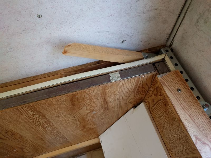
I guess that I could put steel all the way accross the front and see what breaks next. Perhaps welding in some outriggers is the next step, though. I don't have any skirting on my HILO, so this would involve cutting a square section out of the frame and inserting the 2" box through that and welding in place, which appears to be how the rear outrigger is installed.
|
|
|
|
|
08-12-2020, 10:29 AM
|
#18
|
|
Site Team
Join Date: Jul 2010
Location: Pine, AZ
Posts: 4,548
|
The skirting on my HiLo doesn't provide any support. The outriggers are secured to the steel frame crossmembers at each end Surely, your trailer has those crossmembers. The longitudinal frame on my HiLo has NOT been cut at all.
- Jack
|
|
|
|
|
08-13-2020, 08:27 PM
|
#19
|
|
Member
Join Date: Mar 2018
Location: Illinois
Posts: 39
|
I had the same problem in the front corner PLUS a bunch of other structural troubles. On my 2200, there is a 1" square steel tube skeleton on each side and another skeleton in the front. A wooden beam runs the length each side and across the front. My beams were rotted and the screws that held the side & front skeleton together had rusted out. Attached are some pics showing some of the issues. My solution was a big rebuild of the front & long side. Hope this helps
|
|
|
|
|
08-14-2020, 01:43 AM
|
#20
|
|
Member
Join Date: Jun 2013
Posts: 37
|
Quote:
Originally Posted by On The Road Again
...On my 2200, there is a 1" square steel tube skeleton on each side and another skeleton in the front. A wooden beam runs ... across the front.
|
Those photos are really helpful.
I had already gathered that their was a weird gap in the upper section width framing (photo 1, black rectangle in the middle lower part of the image). If I put a piece of steel accross the top of that framing, I won't be able to thru bolt it because tightening the nuts at the ends of the allthread will compress the wood into that gap and destroy the framing.
Photo 2 doesn't really surprise me. It seemed like the curve was supported with steel there. Is there a piece of wood that runs from side to side or steel?
Photo 3 brings up an important question in my mind. The steel bar running through the center of the image is not attached in any way to the side of my trailer. It appears to be attached to the width framing, but not at the ends. This has always struck me as odd, and is possibly the source of the weakness I'm seeing.
__________________
|
|
|
|
|
|
 Posting Rules
|
You may not post new threads
You may not post replies
You may not post attachments
You may not edit your posts
HTML code is Off
|
|
|
|
 » Recent Threads
 |
|
|
|
|
|
|
|
|
|
|
|
|
|
|
|
|
|
|
|
|
|
|
|
|
|
|
|
|
|
|
|
|
|
|
|
|
|


 Linear Mode

